Home

beruhigen Konservierungsmittel Überlegenheit vt transistor schwingen Küste Draussen

Panasonic PN205L-NC.VT Transistor

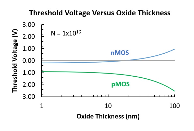
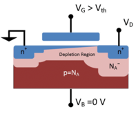
Threshold voltage - Wikipedia

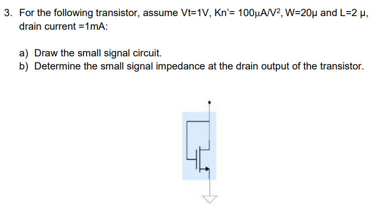
Solved 3. For the following transistor, assume Vt=1V, Kn'= | Chegg.com

The NMOS transistor in the circuit of Fig. P5.44 has Vt = 0.4 V and kn = 4  mA/V2. The voltage at the - YouTube
The NMOS transistor in the circuit of Fig. P5.44 has Vt = 0.4 V and kn = 4 mA/V2. The voltage at the - YouTube

The measured and the projected transistor Vt variation (unstressed) as... |  Download Scientific Diagram
The measured and the projected transistor Vt variation (unstressed) as... | Download Scientific Diagram

MOS Transistor Definitions

a) N-channel multiple VT, fully depleted SOI-transistor with a back... |  Download Scientific Diagram
a) N-channel multiple VT, fully depleted SOI-transistor with a back... | Download Scientific Diagram
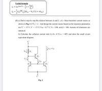
Answered: Useful formula VCE ic = Ise"BE/VT . In… | bartleby

IEDM 2017 - Controlling Threshold Voltage with Work Function Metals -  SemiWiki
IEDM 2017 - Controlling Threshold Voltage with Work Function Metals - SemiWiki

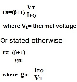
How to Calculate Rπ (Rpi) of a Transistor

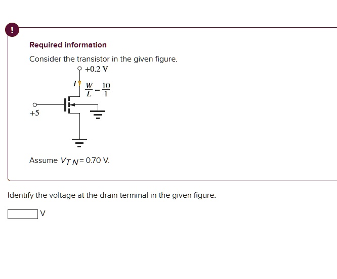
SOLVED: please help me with this Required information Consider the  transistor in the given figure +0.2 V W-10 +5 Assume VT N= 0.70 V ldentify  the voltage at the drain terminal in
SOLVED: please help me with this Required information Consider the transistor in the given figure +0.2 V W-10 +5 Assume VT N= 0.70 V ldentify the voltage at the drain terminal in

MOS Transistor Definitions

ECE 255, BJT and Operating Point

In the circuit shown below, the transistor operates at ID=0.4 mA and VD=0.5  V. The NMOS transistor has Vt=0.7 V,μ nC∝=100μ A/V2,L=1 μ m and ω =32 μ m.  Assume λ =0.
In the circuit shown below, the transistor operates at ID=0.4 mA and VD=0.5 V. The NMOS transistor has Vt=0.7 V,μ nC∝=100μ A/V2,L=1 μ m and ω =32 μ m. Assume λ =0.

IC versus the overdrive voltage V G − V T 0 measured in saturation on... |  Download Scientific Diagram
IC versus the overdrive voltage V G − V T 0 measured in saturation on... | Download Scientific Diagram

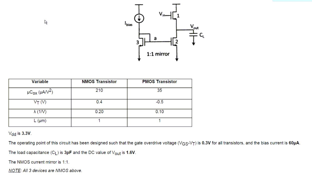
Solved bias ut 1:1 mirror Variable NMOS Transistor PMOS | Chegg.com

The PMOS transistor in the circuit of Fig. P5.49 has Vt = −0.5 V, μpCox =  100 μA/V^2, L = 0.18 μm - YouTube
The PMOS transistor in the circuit of Fig. P5.49 has Vt = −0.5 V, μpCox = 100 μA/V^2, L = 0.18 μm - YouTube

Threshold voltage - Wikipedia

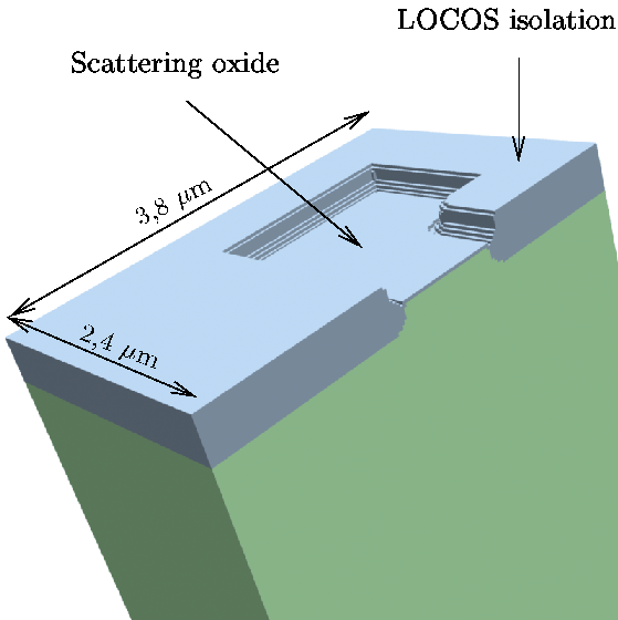
5.4.1 Threshold Voltage Adjust Implantation of an NMOS-Transistor

transistors - What do \$V_{TN}\$ and \$V_{T}\$ stand for in a MOSFET? -  Electrical Engineering Stack Exchange
transistors - What do \$V_{TN}\$ and \$V_{T}\$ stand for in a MOSFET? - Electrical Engineering Stack Exchange
ASIC-System on Chip-VLSI Design: Multiple Threshold CMOS (MTCMOS) Circuits

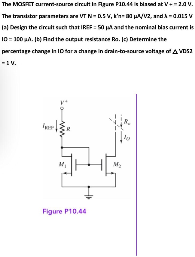
SOLVED: The MOSFET current-source circuit in Figure P10.44 is biased at  V+=2.0 V. The transistor parameters are VT N=0.5V,k'n=80A/V2,and =0.015V  aDesign the circuit such that IREF=50uA and the nominal bias current is
SOLVED: The MOSFET current-source circuit in Figure P10.44 is biased at V+=2.0 V. The transistor parameters are VT N=0.5V,k'n=80A/V2,and =0.015V aDesign the circuit such that IREF=50uA and the nominal bias current is

SOLVED: An NMOS transistor has a threshold voltage, Vt, 0.4 V and a supply  voltage of VDD=1.2 V. Thermal voltage, VT , is 26 mV at room  temperature(300 K). Celsius to Kelvin
SOLVED: An NMOS transistor has a threshold voltage, Vt, 0.4 V and a supply voltage of VDD=1.2 V. Thermal voltage, VT , is 26 mV at room temperature(300 K). Celsius to Kelvin

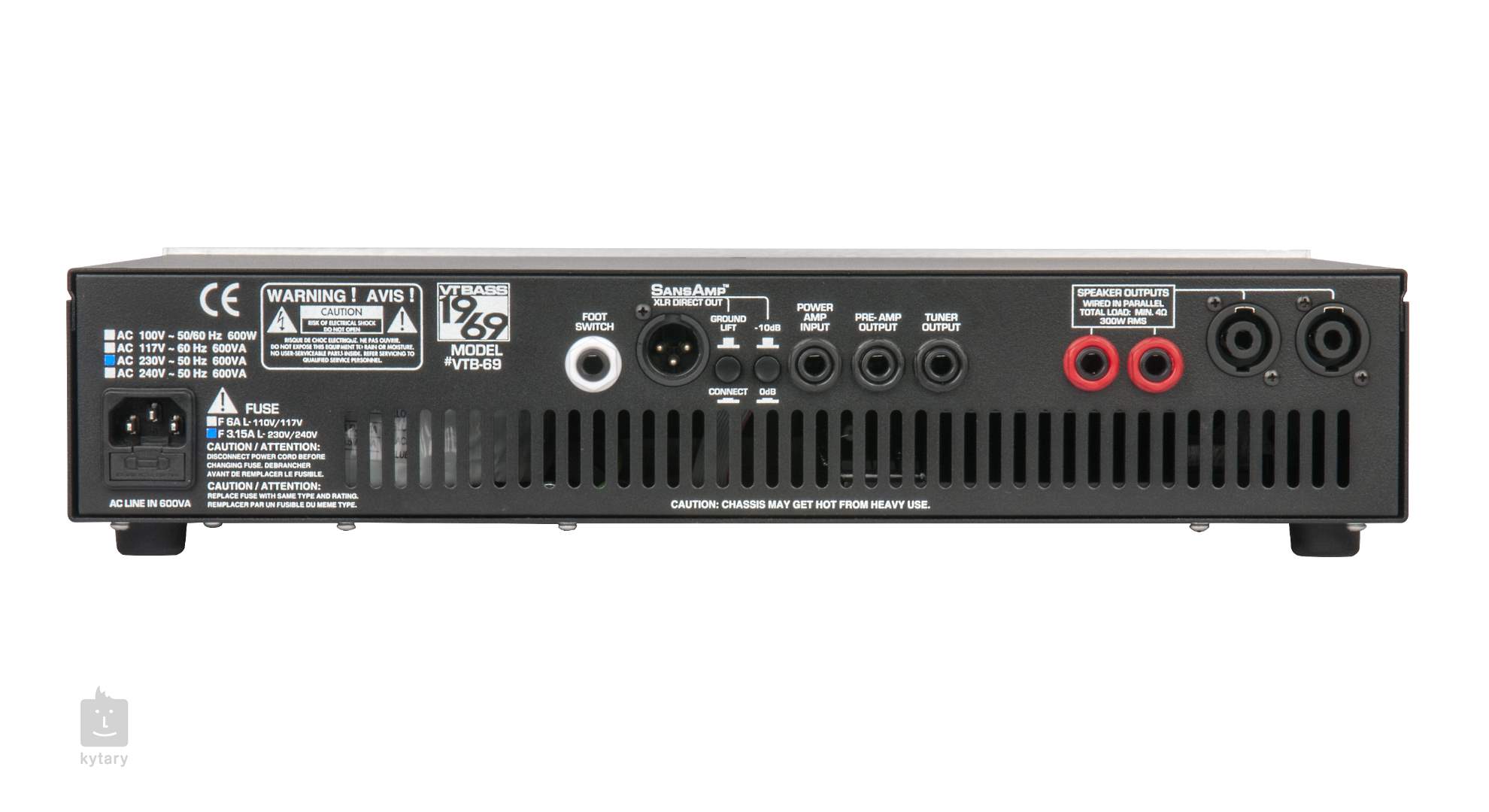
TECH 21 VT-1969 (erweitert) Transistor-Verstärker für Bass

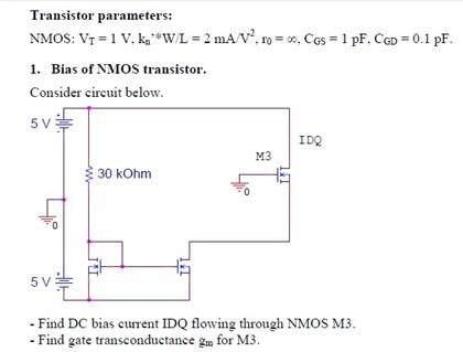
Transistor parameters: NMOS: VT = 1 V, kn'*W / L | Chegg.com

Bipolar Junction Transistors

Extraction of Vt and Kn using a diode-connected transistor. Note that... |  Download Scientific Diagram
Extraction of Vt and Kn using a diode-connected transistor. Note that... | Download Scientific Diagram

Correlation of threshold voltage (Vt) on long channel transistors with Vt  implant dose determined by high precision SIMS | Semantic Scholar
Correlation of threshold voltage (Vt) on long channel transistors with Vt implant dose determined by high precision SIMS | Semantic Scholar